The following example will show you how to use SE::Column to determine the flexural capacity of a T beam. This example is from book Design of Concrete Structures 14th edition by Arthur H. Nilson et al. page 113.
The calculated flexural capacity with SE::Column is compared with the value from the book and they matches very well.
Below is the T beam information
T beam dimension: Total beam height 30”, flange width 28”, flange thickness 6”, web thickness 10”
Reinforcement: (6) #10 Distance from centroid of rebar group to top of beam is 26” (2) #10 on the compression side is ignored.
Concrete compressive strength: f’c=3 ksi
Steel modulus of elasticity: 29000ksi
Steel yield strength: 60ksi
Phi factor: use 0.9
We use the Kip, in unit system by default.
Step 1
Draw 8 bars with Draw–˃Reinforcement–˃Single Bar. Each bar shall represent the vertex of the T beam. The bars here are only used to locate the vertex of the rectangle. It will be deleted later. Instead of doing this, you can set up the grid for drawing the rectangle in the next step.
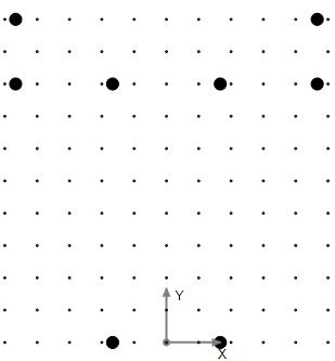
Figure 1.0 Step 1
Step 2
Draw the T shape with Draw–˃Shape–˃Irregular Polygon based on the vertex information from step 1. Delete the bars from step 1.
Make sure the snap to point is on.
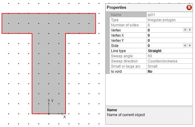
Figure 2.0 Step 2
Step 3
Draw the reinforcement with either Edit–˃Manage Reinforcement dialog or use Draw–˃Reinforcement–˃Single Bar.
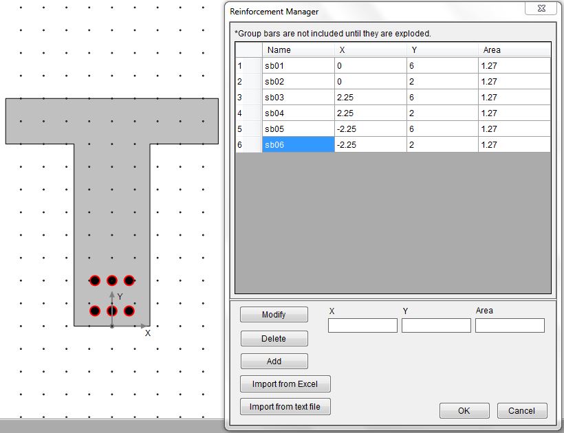
Figure 3.0 Step 3
Step 4
Select uniaxial bending from Parameters–˃Criteria. Leave the design code as it is.
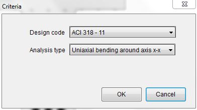
Figure 4.0 Step 4
Step 5
Input concrete compressive strength, reinforcing steel yield strength and steel modulus of elasticity using Parameters–˃Material.
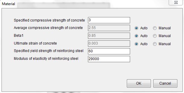
Figure 5.0 Step 5
Step 6
Display the resistance factor dialog with Parameters–˃Resistance Factors.
Leave the resistance factors as it is. In this case it will be a tension-controlled case and the phi factor is 0.9.
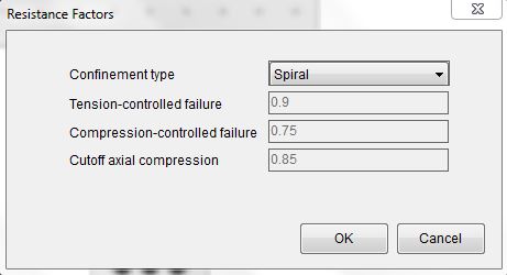
Figure 6.0 Step 6
Step 7
Display the loads dialog with Parameters–>Loads.
Input Pu=0 kips and Mu=-1000kips-in. The reason we use 0 kips is because the beam has no axial force. We use a negative bending moment because beam compression side is on the top and the bending moment is in the negative x direction. This step is optional. You can find the flexural capacity from the generated interaction diagram directly. However, defining this load will let the program report flexural capacity corresponding to zero axial force directly.
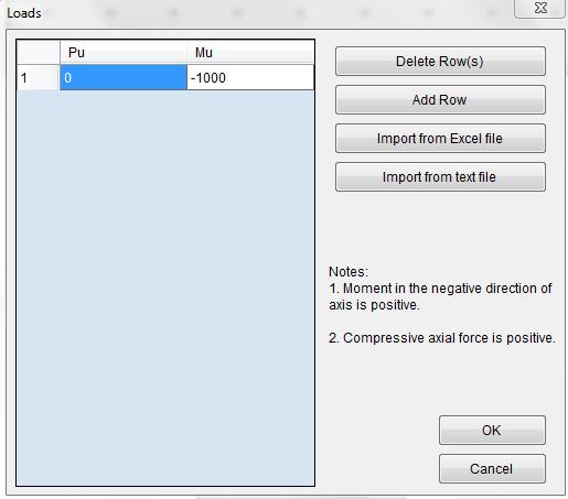
Figure 7.0 Step 7
Step 8
Run the analysis with Analysis–˃Run. The output tab will be activated automatically. The ɸMn on the load tab is -9373.69kip-in while the value from the book is 9370kip-in. The neutral axis depth is 8.41” and the value from the book is 8.39”. They all match very well.
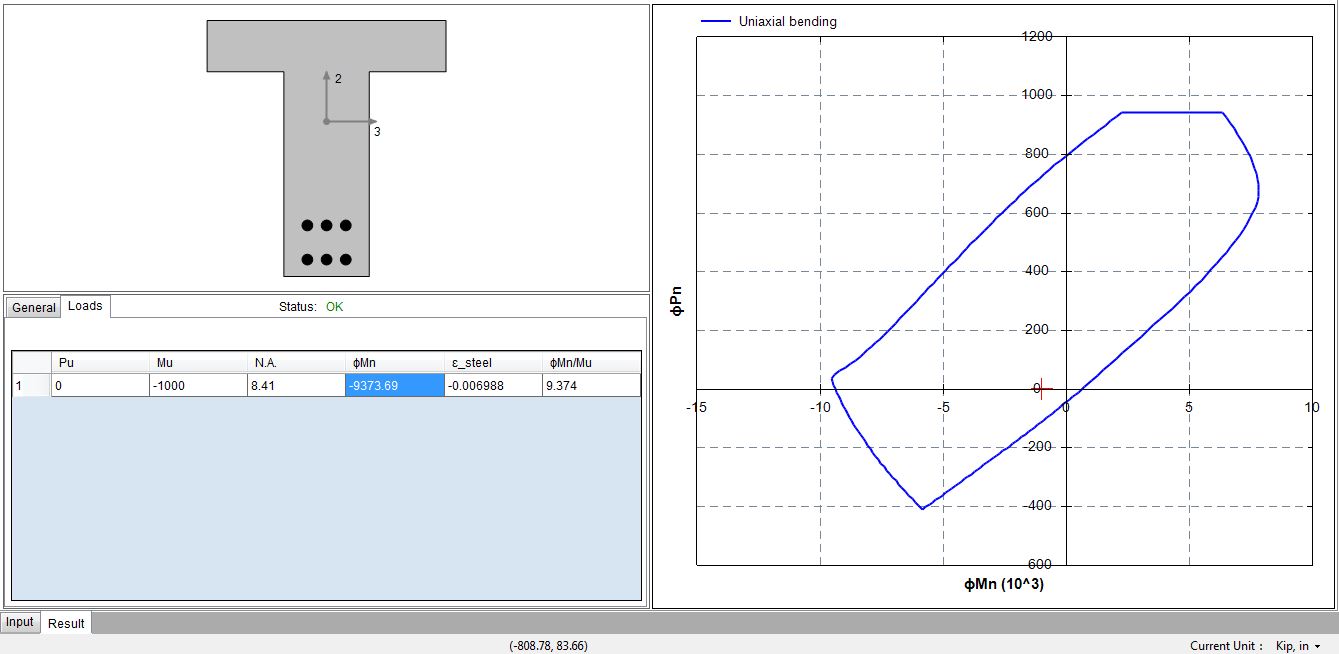
Figure 8.0 Step 8